Four independent throttles on a single card.
Inertia can be applied to each channel.
Motor speed detection feedback can maintain constant train speed (optional)
Built-in adjustable track circuiting (threshold current is user-defined)
Scale independent up to 'G'. Only a few components are changed for different scales.
Integral turnout drive circuits for slow action turnout motors such as Tortoise, Fulgarex, Lemarco and Conrad.
Foldback current limiting (shutoff output until short is removed) to protect the locos as well as the QTU itself.
Dead-reckoning system integrates feedback to keep track of how far each loco has travelled along the track.
Can be used as manual throttles, autonomous throttles (can make decisions on its own), or computer controlled throttles.
Several boards can operate from a single transformer.
Integral reversing relays and spare power routing relays.
Fully configurable Logic function block to define how the board is used and what each signal does (configuration defined on a computer and downloaded into the QTU).
Eight analogue inputs for speed, inertia and other control possibilities (defined in the logic function block).
General purpose input and output lines.
Compatible with RS232, RS485 and RPC interface standards up to 56,700 baud.
Configured and/or controlled using our free Tcc software.
The QTU is intended to be a throttle (controller) unit for use on a model railway. In fact four throttles are built into a single card. These four throttles can be used as conventional manual throttles by connecting potentiometers for speed and switches for brake and reverse. Inertia potentiometers can also be added so that speed changes are gradual. Track circuiting (current detectors) are built-in and these could be used to drive lights on a control panel.
Four throttles were put on a single card because that was the most cost-effective combination. Fewer circuits would save only a few pennies, and more circuits would probably overload the processor and would add significantly to the cost.
The output waveform is unsmoothed DC (rounded pulse) as this produces good slow running, no overheating and minimal motor noise.
The throttles detect short circuit conditions (user-definable current limit) and shut off the output for half a second. This reduces the chance of motors overheating if they stall.
A single transformer is required for all four throttles. In fact if it is rated high enough you could use a single transformer to drive all the trains on your layout. The benefits of this scheme are:
To allow throttles to be mounted under the baseboard whilst keeping mains voltages away.
Keep track feed wiring to a minimum length.
Simplifying power routing to crossovers and similar structures.
Reducing the cost of transformers (and associated opto-isolators).
The trade-off is that you must break both tracks between sections and connect the throttle to both tracks. Note that the QTU is not compatible with common return layouts as this creates a short if any section is placed in reverse direction.
Motor speed can be controlled by measuring the voltage generated between output pulses (commonly called back-EMF) and adjusting the output voltage to maintain constant motor speed. This means that gradients and curves have minimal effect on train speed and making stalling virtually impossible. This feedback control is an option that is part of the configuration you can download into a QTU.
A QTU could be considered to be a four-channel super BC3 (a Merg throttle kit) - in other words an autonomous throttle. Autonomous throttles can operate with minimal or no manual intervention and will stop trains running into the back of one-another. The operators can concentrate on setting routes. The autonomous behaviour works by having one throttle per track section (one QTU per four track sections) and each feeds an 'occupied' signal to the previous throttle. If one throttle detects a train and also receives an indication that the next section is occupied then it will slow and stop the second train to avoid a crash. Only when the next section is free will the train be allowed to continue.
One key concept mentioned in the previous paragraph is one throttle per track section. This means that power wiring is minimal - you just install QTUs under the baseboard, near to where they are required and typically you have no external power switches or relays. The QTU can of course be used in a conventional one throttle per track loop, or even with progressive cab control but the extremely low cost of throttles means that the extra wiring and relays is hard to justify unless you are running a manual control layout.
The QTU also has a computer interface (RS232 and RS485) which permits a computer to monitor whats happening (in case the computer is driving some kind of display board or window) or take control of one or more throttles.
Input and output lines are available on the QTU so that external sensors, signals, turnouts etc. could be connected. These can be controlled by an attached computer, or the QTU itself can be configured to drive them. For example the sensors could be used to control where a train stops, or signals could be automated - all just using QTUs - without a computer!!!
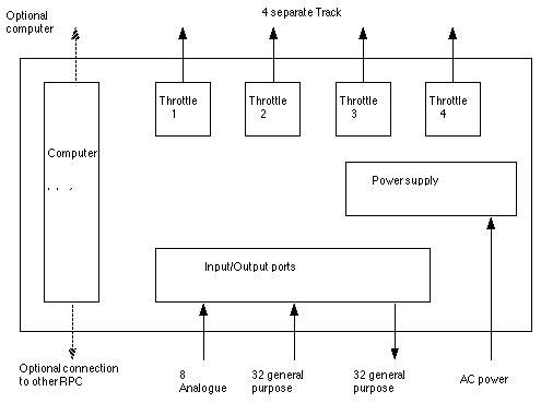
The QTU consists of four separate throttles, I/O capability and computer interface that might be represented by the following diagram. Everything inside the large box in inside the QTU, either in the hardware or in the firmware residing in the processor.
As the QTU is so flexible it is rather confusing to consider all its capabilities in one go and so this description will focus on the three principal operating modes:
1. Manual - used as a conventional throttle
2. An autonomous (BC3-like) unit
3. A computer controlled throttle
These three operating modes are not distinct - you can have any combination of all three but it is simpler to start off thinking about each in turn.
Each throttle has its own speed potentiometer, brake switch and reversing switch. It then operates as a conventional throttle, the board potentially becoming four conventional throttles.
The brake and reverse switches are all connected to some of the 32 general purpose input lines available on the QTU. These lines can influence the throttle, as defined by their function names, but can also influence the 24 general purpose output lines. In addition the current detector built into each throttle can also influence the output lines.
Optionally
other functions are available:
Extra potentiometers may be connected to define inertia applied during acceleration and inertia during braking.
Eight spare analogue inputs are available and any function may be taken from any input (so perhaps all four throttles can share a single braking inertia knob).
A 'stop here' switch may be added which causes the next train to stop on its track section. When current is detected the brake is applied and the train will gradually come to a halt using the braking inertia setting. When the switch is turned off the train will be allowed to continue.
In manual operating mode power routing can be any strategy you would use with other throttles, provided both tracks are isolated from adjacent sections. This need for isolating both tracks comes from using a common transformer to feed all the throttles on the QTU - the 'common return' is on the transformer side of the throttle and so one side of the track cannot be used as common return. Although this means more track wiring it saves money by only needing a single transformer for all the throttles instead of a secondary winding for each throttle (as is normal with common return track layouts).
An autonomous throttle is one that can drive the trains without manual intervention, and without computer control.
In simple terms autonomous throttles signal track occupancy to the throttle controlling the previous section (the section that a train comes from to reach the current section). Thus each throttle can see whether the next section is occupied or not. If the next section is occupied then the train must stop within the present section. If you want to maintain a whole track section clearance between your trains then this can be handled also, with exactly the same wiring. This flexibility comes from the 'Logic expression block' explained later. For now just assume that inputs and outputs can be made to do whatever you want them to do.

If
using only the built-in track circuits (current detectors) then as
soon as a loco reaches the start of the track section it will slow to
a halt if the next section is occupied. The precise location that the
train stops is not controllable as it depends upon train
characteristics and track curvature and gradient. Different trains
are likely to stop at different positions, but if the inertia is not
set too high they should all stop within the section.
Where tracks connect through turnouts the link wires should be connected through a switch mounted on the turnout so the concept of 'next' and 'previous' is maintained when turnouts change. The turnouts could be controlled by a switch panel as normal.
Where one throttle follows another in the same QTU (possibly across a turnout) then there is no need for a physical link wire - the QTU can be configured internally so that one channel watches another instead of an input pin.
In an autonomous system it might be common for all throttles to have their speed settings at the same value. To do this you configure all four throttles in each QTU to take their speed input from a single analogue line, perhaps adcuser0, and then wire a single potentiometer to the adcuser0 line of all QTUs in the layout.
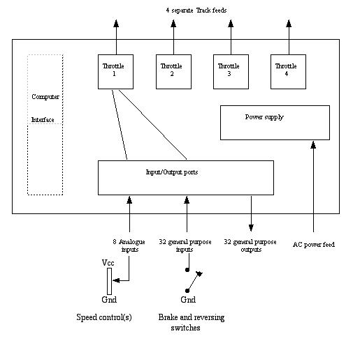
The diagram illustrates the throttles (one on each of two separate QTUs for clarity) connected and described. Both throttles are fed from the same speed and reversing switches. An output on the second throttle (shown on the right) connects to an input on the left hand throttle.
If one or more sensors were placed by the track that could detect the presence of any part of a train (such as an infra-red light beam) and the outputs of those sensors were connected to the throttle then the throttle could slow and stop the train just as it reached the end of the section (just in front of the signal placed there) and perhaps only signal clear to the previous section when the train has completely entered (or departed if you prefer) the current section - this allows the system to handle trains of any length).
Each throttle could have a three aspect signal placed at the start of the track, and driven from a configuration based on the following truth-table:
Signal light lit        This track occupied             Next track occupied
RED                     true                            don't care
YELLOW                  false                           true
GREEN                   false                           false
Again this illustrates another example of using inputs and outputs for any function you require. The QTU does not have the above truth table built-in, but can be configured to implement it if required.
This illustrates another of the limitations of simple autonomous mode - there is insufficient information available to drive signals properly (ie. stay red unless a train is coming), or to drive 4 (or more) aspect signals.
The QTU supports the RPC-style stack interface in the following guises:
It can connect directly to a controlling computer directly by RS232, but this means you can only have a single 'stack' of RPC modules.
A QTU can be connected as a 'slave' module from another QTU. This means you might have one QTU connected to a PC and several RPC modules including QTU boards connected as a stack from the one 'master' QTU. In theory you can have up to six slave QTUs off a master.
If several 'stacks' are required then one QTU can connect to the computer using RS232, and this is then buffered out as RS485 to other QTUs. No RPI or RS485 buffer modules are required with QTUs - they are their own RPI and have built-in RS232 to RS485 buffers.
A DIL switch on the board is used to define the stack address - each stack needs a separate address so that the computer can talk to them individually. This allows for up to 32 stacks each containing up to 7 boards - more than enough for a large layout!
The computer can also read the current speed setting (after inertia has been applied), the current feedback voltage, current consumption and the time measurement counters described later in this document.
Apart from controlling the throttles the computer has access to the general purpose I/O lines. Each output line can either be driven directly by the computer, or by (or through) the logic function described later. The input lines can all be monitored by the computer (and also by the logic expressions).

There is no need to constrain your ideas to manual, autonomous or computer controlled - it is quite possible to have some combination of all three, or even to use different modes at different times as your mood takes you.
For example you could start with a layout operating in purely manual mode, with one or two QTUs (providing the same number of throttles you would like to have normally). If this is implemented by sectioning the track as if you had a more sophisticated system, but then connect groups of track sections back together as if you hadn't done the extra track breaks. This then is the manual operation starting point.
Later on when inspiration takes you, add some more QTUs so each (smaller) track section has its own throttle. For compatibility connect speed, direction and brake inputs up in the groups you had before adding the extra throttles. You are now back to square 1, but with more hardware.
Add the links from each throttle to its predecessor, through turnout mounted switches if necessary. Remember that links within a single QTU board are not required. While all this is going on you still have fully functional manual mode.
Once enough links are in, re-configure some QTUs to run manual mode augmented by autonomous mode. This means that each of your larger track sections can handle more than 1 train and they will follow one another in a controlled fashion. Adding 'Stop here' buttons and/or randomised station stops can enhance your primarily manual control layout.
The next step might be to connect all the RS485 ports together, and an RS232 port to a computer. You might have done this already to simplify experimenting with logic equations.
Run our Tcc software on the computer to monitor the state of each throttle and get it to display an animated layout board (CTC panel) showing a diagrammatic representation of your layout and indicating where each train is.
Becoming slightly more adventurous one could use the computer to take control of part of the layout - perhaps automating a shuttle service, or even taking control of the mainline while leaving the more interesting termini and goods yards to manual control.
Even with the computer connected and either monitoring or taking some control it is possible to reconfigure the QTUs back to just manual operation. Better still have both modes installed in each QTU and switch between them using a single master switch that connects to an input on all QTUs.
NOTE: This is not currently implemented
Basic autonomous mode is restricted to just signalling occupancy from one section to the previous one. It is of course possible to switch several signals between throttles and this would permit more information to be passed, possibly in both directions but the wiring becomes rather complex.
If the link wire between sections carried more than just a single bit of information (occupied or free) then more advanced control and/or signalling would be possible.
In place of a link wire connected to the general purpose inputs and outputs (as used above) a link wire connected to dedicated pins on the microprocessor is used. These pins are used as bi-directional serial links. The status of each section is sent to its neighbours periodically. Instead of a single bit, the status is now a whole byte, and other information is also carried including throttle speed setting, slow speed and output voltage.
Logic expressions (see next section) can define the contents of 7 bits of this status byte (the other bit being the current detector output), and can use the status information received from its neighbours.
With advanced autonomous mode this status byte is passed to both the previous section (as with basic autonomous mode) and also to the next section. It is of course possible to use other bits to indicate that the next section is occupied (so that the state of the next two sections are available). This would permit signals to be driven perhaps on the following lines:
Signal colour   previous        this            next            next-next
colour          section         section         section         section
RED             free            x               x               x
                x               occupied        x               x
Yellow          occupied        free            occupied        x
double-Y        occupied        free            free            occupied
Green           occupied        free            free            free
No doubt you will have other ideas of how signalling should work and you should be able to implement any scheme you wish quite easily with advanced autonomous mode.
Basic autonomous mode uses a single speed setting for the whole layout (or at least a whole track loop). Advanced autonomous mode allows each train to have its own speed settings (for full speed and a separate value for crawl). As trains travel around the layout their settings can travel with them.
The observant reader will immediately ask where these speed settings come from if a computer is not in use. When a train is detected at startup, power can be applied gradually until the train starts moving - that value can be defined as crawl. Full speed can initially be set to some higher value, or set on a potentiometer and adopted as full speed at the press of a 'save speed' button.
The link wires can be connected through turnout switches in exactly the same manner as for basic autonomous mode and so 'upgrading' to advanced autonomous mode is simply a matter of reconnecting these wires to the dedicated pins on the processor and reconfiguring the QTUs.
In general terms a QTU has a number of inputs (the 32 single bit inputs, the 8 analogue inputs, data received from the computer, the output from the current detector and pre-configured data). These inputs need to be fed somehow to the outputs (32 single bit general purpose outputs, throttle speed, direction, brake and inertia and of course data back to the computer). The logic function block is the magic that interconnects all of these signals in whatever manner you require.
Any logic expression may be configured (within the available memory constraints) to connect any available input to any available output. The 'stop here' function is simply an example of one such expression.

The
logic expression supports the following capabilities:
1. Copy one data bit to another
2. Binary AND
3. Binary OR
4. Binary Exclusive-OR
5. Data inversion (NOT function)
6. Memory (software flip-flops)
7. Random probability
8. Time delays
9. Time measurements
10. Conditional evaluation
11. Copy one analogue input to throttle speed or inertia, or to define the random probabilities or time delays.
12. Take the average of two analogue levels
13. Convert a centre-zero input into a direction bit, and a plain level.
The first five items in the above capability list are conventional logic expression building blocks (the above example uses copy, binary AND and binary OR). The others deserve more description and are defined below.
As a simple example consider the 'stop here' button. If input switches are called 'BrakeSw', 'ReverseSw' and 'Stop_here', the current detector signal is called 'Occupied' and the outputs that drive the throttle are called 'brake0' and 'reverse0' (ie, you are using throttle 0) then the basic functions may be implemented as:
brake0 = BrakeSw OR (Stop_here AND Occupied)
reverse0 = ReverseSw
Autonomous mode is implemented by defining suitable logic expressions and connecting an occupancy wire from each section to its predecessor. For example an expression would copy the current detector output to an output pin, and another expression would drive the brake from the input connected to the next track. For example:
Link_Out = Occupied
Brake0 = BrakeSw OR (Link_In AND Occupied)
These two expressions would implement a simple tail-chasing behaviour where a train would slow and perhaps stop if it were catching up to the train in front.
Where one throttle follows another in the same QTU then there is no need for a physical link wire - the expressions could simply monitor the Occupied status of the 'next' throttle within the QTU by specifying the appropriate detector. For example if throttle 1 is followed by throttle 2 and they have Occupied1 and Occupied2 as their current detector outputs and Throttle_Brake1 and Throttle_Brake2 then ...
brake1 = Brake1Sw OR (Occupied2 AND Occupied1).
The logic expressions can be used to make the autonomous mode more 'intelligent', perhaps by controlling turnouts, perhaps by controlling signals or perhaps detecting the start and end of each train more accurately than just a current detector and unmodified rolling stock can.
The more complex functions of the logic function block are defined as:
The QTU has several binary memory locations for use in scripts (called memory0 to memory31).
Random probabilities are implemented as data that takes a random value when you write to it. Simply write a 1 and then read back a 1 or a 0 that is generated randomly.
We could for example make the occasional train stop at a station. Of course we need something to allow the train to start off again. Suppose we have a 'Resume' button (in addition to the signals defined above). The expressions might look something like:
random0 = Occupied
memory0 = (memory0 OR random0) AND !Resume
brake0 = BrakeSw OR (Stop_here AND Occupied) OR memory0
When the current detector detects a train arriving the Occupied signal goes to a 1. This triggers the generation of a random value in random0. If random0 is a 1 then memory0 is set to 1 and brake0 is driven, thus stopping the train. When the Resume switch is pressed (goes to 1) then memory0 is cleared (see the memory example above if you are confused) and the throttle brake signal is removed so the train can carry on.
The percentage chance of a random number being a 1 or a 0 can be configured permanently (in EEPROM) or can be taken from an analogue input on one of the eight analogue input lines. The probability is configured by writing to Probability0 to Probability3.
There are four random number variables in a QTU (random0 to random3). Note that a random number variable only adopts its random state after it has a 1 written to it after a 0 has previously been written. This means that the probability of stopping the train is only evaluated once - when the current detector first sees the train. When a 0 is written to a random number variable it always returns a zero.
Time delays are implemented as data that returns to 0 after some period.
Simply write a 1 to one of the four time delay variables and for a while it will have the value 1. Some time later it will revert to 0 of its own accord.
A time delay variable might be used in place of the Resume button to allow the train to continue without manual intervention. Therefore an operator might press a Stop here button and the next train could be brought to a gentle stop at a station, wait a while and then carry on while the operator concentrates on other issues.
random0 = Occupied         // random0 might be 1 or 0 when current is detected
timing0 = random0             // If Rand is set to 1 then Time is set to 1 for a while
brake0 = BrakeSw OR (Stop_here AND Occupied) OR timing0
The actual time the variable stays set to 1 can be configurable in EEPROM or can be defined by an analogue input line (eg a potentiometer labelled 'Time in station'). The actual delay is in units of 100ms, and can vary from 0.1s to 25.5s
There are four time delay variables in a QTU.
Time measurements are only used in computer controlled mode.
A time measurement variable increments a 16 bit counter as long as that variable is set to 1. When cleared to 0 the counter stops counting. When set to 1 again the counter starts again from zero. The counter has a resolution of 10ms and so can measure from 0.01s to 655.35 seconds (nearly eleven minutes).
The counter cannot be read from the logic expressions - it is only available from the computer interface.
A typical use might be to measure the speed of a train - or rather how long it takes to travel a known distance. Perhaps by measuring how long current is detected on a section, or the time between two position sensors.
Measuring the actual speed of a train can be used to ensure they all run at sensible speeds and to adjust for speed changes as locos warm up - this is an amazingly significant factor, though the feedback mechanism does help control this.
Conditional evaluation is a slightly more complicated capability.
Part of the expressions in memory might be evaluated only when some other condition is true. This could permit several different sets of expressions to be stored at once, with a switch defining which set to use. For example different expressions might be used if the QTU was being driven by a computer from those in use when a manual operator was in control.
By analogue inputs we mean data that takes more than two values. The 32 general purpose inputs and outputs are binary - that is they can only be 0 or 1 (high or low). By contrast speed and inertia settings can take many levels - the throttles handle 256 different speed settings.
The 8 analogue inputs together with the speed, minimum speed and inertia settings from the computer, and any constant values stored in EEPROM may be routed to any of the defined functions that use analogue levels. These functions are:
Four throttle speed inputs called speed0 to speed3
Four throttle inertia inputs called inertia0 to inertia3
Four random number variables described above. the analogue level defines the probability of generating a 1.
Four timers that might be used to control station stops. The level defines how long the stop will last.
Routing of these analogue signals can be dependant upon binary equations. For example three different inertia settings could be used for each throttle dependant upon whether the train is running normally, slowing for a station, or braking at a sensor.
Inputs may be treated as varying from 0 to 255, or can be treated as centre-zero. Centre-zero inputs have their direction extracted (which becomes a binary input to be used in binary equations such as being fed to a throttle reverse input), and the remainder scaled back up by doubling. The centre zero is actually a window to make centring a knob possible.
The non-volatile configuration data is held in the 512 byte EEPROM inside the processor. This configuration data includes the following:
1. Whether to use feedback or not.
2. The amount of filtering for each input pin, and for the current detectors.
3. The logic expressions
4. Which analogue input is used for each function (Inertia, Slowdown inertia, Braking inertia, Station stop probability and station stop duration) on each channel.
This configuration data can be changed by sending special messages from the PC. Once changed the configuration is retained even after power down.
NOTE: a computer is required to change QTU operating parameters even if you do not use a computer in operating the railway.
The tcc program includes configuration dialogs and the capability to download the configuration to any given QTU in the system. Message formats and configuration data formats are available should anyone wish to write their own configuration program, or integrate QTU configuration into their own railway control application.
Nearly all the functions are handled by a single-chip microprocessor - an AVR chip from Atmel corp, the ATMEGA32. This chip has the following resources:
1. 32 8-bit registers - good for reducing access to main memory
2. 2048 bytes of SRAM
3. 1024 bytes of EEPROM - used to save configuration and logic expressions
4. 32K bytes of FLASH to store the firmware
5. UART - used for RS232 and RS485 interfacing
6. SPI - used to drive D/A converter and I/O registers
7. Analogue comparator - used to detect zero crossings for synchronisation
8. 8-bit timer 0 - used to generate clock timing when QTU is in master mode
9. 16-bit timer 1 - used to generate a 1ms interrupt to trigger regularly executed code.
10. 8-bit timer 2 - used as a phase-locked loop to generate analogue sample interrupts that synchronise to the zero crossings of mains frequency.
11. 8 channel 10-bit analogue to digital converter. With external multiplexors this is extended to 16 channels - 8 for the throttles and 8 spare for potentiometer inputs.
12. Watchdog timer - resets the QTU if the firmware should hang.
13. 2 external interrupt pins - used for the RTS line in RS485/232 mode, and RPC Clock and load lines in slave mode.
14. In-system programming - the firmware can be upgraded without removing the chip from the board.
15. 32 general purpose I/O lines (some share functions with other interfaces such as UART, SPI etc).
This is one of the larger AVR chips, running at 16MHz. It executes one instruction per cycle and so is capable of 16 million instructions per second (16 MIPS). Instructions that access SRAM or EEPROM take two cycles.
In addition to the processor the QTU has two 32-bit shift registers connected to the SPI port. These expand the processors I/O capabilities and provide the general purpose inputs and outputs that the logic expressions use.
A four-channel D/A converter is also connected to the SPI port and this is used to output samples of the waveform that drives the locos. This voltage is amplified by an op-amp and buffered with a darlington transistor.
The A/D converter in the processor samples the voltage on the track and also the current consumption. The voltage measurement is to measure feedback voltage. Analogue multiplexors increase the number of available channels to 16 to provide 8 spares for external potentiometers.
The serial interface to the controlling computer can either be unbuffered - when the board is a slave module in an RPC stack, or driven with RS485 buffers to an RS485 bus, or with RS232 buffers directly to a serial port on a computer. Both RS232 and RS485 can be equipped simultaneously so that other RS485 QTUs (or RPIs) can share a single RS232 port on the PC.
Four of the output lines drive relays that function as reversing switches. Four more drive unattached relays that could drive external devices, or perhaps route power to sidings. Some more outputs can drive turnouts with the four on-board turnout motor drivers - these can be equipped to drive solenoid motors and tortoise motors.
The only other significant hardware is the power supply. This operates as follows:
15-18 VAC is received from the main feed transformer (that could feed several QTUs if required). This is rectified but not smoothed and used as main power to the trains (throught the darlington transistor). A 12V linear regulator generates 12V for any attached electronics that require it such as IRDOT sensors and DPR modules. A 5V regulator generates main power for the on-board electronics and attached RPC stack. Separate rectifiers produce +/- 22-28V for bias signals for any attached FTC modules (8 channel current detectors) - they might be useful for goods yards where one throttle per track is wasteful.
The QTU board has the following connectors, though some are optional extensions:
Stack uplink connector:
10-pin right-angled molex plug to connect to other RPC modules in an existing stack.
OR
Upto three 8-pin RJ45 connectors for RS485 bus
and optionally
9-pin mini-DIN connector for RS232 link direct to computer.
Stack downlink connector: 10-pin molex right-angled socket
General purpose inputs: four 10-pin molex plugs
General purpose outputs: three 10-pin molex plugs
3-pin removable tag block for AC power in (15-0-15V or 18-0-18V)
Power feed to attached modules (FTC bias, DPR relay feed, IRDOT and tortoise power): 10-pin molex connector.
Connections to 4 spare DPDT relays: two 12-pin molex connectors.
|
SK1 |
RS485 link for hand-held control panel |
|
SK2 |
RS485 |
|
SK3 |
RS485 |
|
SK4 |
RL5&6 switch contacts |
|
SK5 |
RL7&8 switch contacts |
|
SK6/SK6a |
Track output. 8 pin: molex, terminal block or pluggable block. |
|
SK7 |
RS232 |
|
|
|
|
PL1 |
Upstream stack. Right-angle molex plug |
|
PL2 |
Downstream stack. Right-angle molex socket |
|
PL3 |
User defined analogue inputs |
|
PL4 |
Comms link for future autonomous mode expansion |
|
PL5 |
Inputs 0-7 |
|
PL6 |
Inputs 8-15 |
|
PL7 |
Inputs 16-23 |
|
PL8 |
Inputs 24-31 |
|
PL9 |
Outputs 0-7 |
|
PL10 |
Output 8-15 |
|
PL11 |
Outputs 16-23, can drive tortoise/conrad/fulgarex motors directly. |
|
PL13 |
Power outputs for accessory hardware. |
|
|
|
|
LN1 |
Output Vcc select PL9 |
|
LN2 |
Output Vcc select PL10 |
|
LN3 |
Output Vcc select PL11 |
|
|
|
|
J1 |
Relay voltage select (link wire) |
|
J2 |
In-system Programming expansion (not normally fitted) |
|
J3 |
Vcc enable (link wire) |
|
J4 |
Links for future expansion. |
|
|
|
|
CN1 |
15-18v AC supply input. 3 pin pluggable terminal block. |
All the intelligence and capabilities of the QTU come from the firmware programmed into its processor chip. This was written in a mixture of C and assembler, and tested on the free simulator package from Atmel, called AvrStudio.
The firmware includes the following sections:
RS232/485 interface module.
RPC stack uplink interrupt routines (for slave mode operation).
RPC shift registers (2 * 16 byte) and downlink interface.
Zero crossing interrupt routine and phase locked loop to generate analogue sample interrupts.
SPI interface code to output analogue samples and drive 32 bit input and output registers. Each analogue output gets ten samples every millisecond.
Analogue input sampling module. Each of the 16 inputs are samples every millisecond.
Message decoder and response generator - for the computer control and configuration messages.
Input signal filters. All 32 input pins and the 4 current detectors are filtered to remove noise, contact bounce etc.
Logic expression executor. This is executed whenever nothing of higher priority is required to run.
Throttle inertia - regulates changes in output voltage using a pseudo exponential algorithm.
Throttle feedback - maintains a steady motor speed rather than a constant output voltage.
Comms links for advanced autonomous mode (NOT implemented yet).