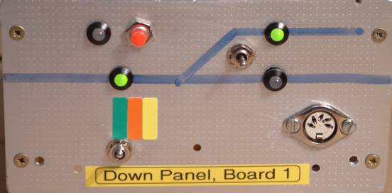
Figure 1: Prototype Control Panel
Writing Scripts for TCC - a Tutorial
TCC (Train Control Centre) software has been described in MERG TB (Technical Bulletin) G16/55. It works via a configuration script that is largely compatible with the scripts used by the CTI system. There is an introduction to the scripts available from the CTI website (TBrain User guide).
This tutorial describes a script used for controlling a simple RPC stack. ( If you find the first parts of the example difficult to follow do not worry - we all operate our layouts differently - just move on down the document a little. H.A. )
The script is enhanced in several stages in order to describe the capabilities of TCC. TCC provides a simulation facility to test a script without the need to attach any hardware. The example scripts can therefore be tried without having to build any control panels or RPC modules.
The RPC (Remote Panel Control System) is available to members from MERG and is fully described in the MERG TBs in the G16/- series. An RPC system consists of a number of kits that build into modules such as the SRO4, SRI4 and DPR mentioned in this tutorial. These kits can be assembled together to form a "stack" of RPC modules. Communication with a computer is via an RPIC (Remote Panel Interface PIC, TB G16/5).
The SRI4 (Shift Register Input 4 bytes, TB 16/19) has 32 input lines that can be driven by open-collectors or similar to provide such functions as point motor feedback, or switch positions.
The SRO4 (Shift Register Output 4 bytes, TB G16/7) has 32 open-collector output lines for controlling devices such as LEDs, PMD (Point Motor Drivers) etc.
The DPR (Double Pole Relay, TB G16/6) has 8 double pole relays which may be used for general purpose switching such as live frogs and section selection.
If the "stack" has to be extended across baseboards, an RSE (Remote Stack Extension, TB G16/24) can be used.
The project mentioned here grew out of an investigation into the concept of "priority cab control". The basic idea is that each section of a layout can be controlled by any one of a number of control panels, arranged in a priority order. The priority order can be different for each section, and it may be that some control panels are not used for some sections.
A prototype was built for a very simple section of track. Three control panels were built on separate baseboards and joined by RSE's. Each panel has a single SRO4 for lighting four bi-coloured LEDs, and an SRI4 to respond to the switches.
|
|
|
Figure 1: Prototype Control Panel |
The track associated with this "layout" is on another baseboard, and includes a DPR for controlling relays, an SRO4 for the point motor driver, and an SRI4 for point motor feedback.
Each control panel is associated with a colour - red, green or yellow - as provided by the bi-coloured LEDs
|
|
|
Figure 2: Control panel schematic |
The first baseboard (the Down Panel or "Board A") is associated with green. For this section it is assumed to be the highest priority. Its switches consist of-
A request push button. When lit LED L1 will be green on all 3 panels.
A centre-off DPDT switch. When in the up direction, the Cab on this panel has control of the section, and L2 is green. When centred, the section is off and L2 is unlit. When in the down direction, control is bypassed to another panel.
A sprung toggle switch. This can only control the direction of the point when this panel has control. The point is moved in the direction of the switch, and afterwards the switch automatically returns to the centre position.
Example 1 is a simple script for just the first control panel, associated with CabA and the colour green. On this board we are only concerned with the control panel containing switches and LEDs.
Controls: {SRO4 Board 1}
        AL1green, AL2green, AL3green, AL4green,
        AL1red, AL2red, AL3red, AL4red,
Sensors:{SRI4 Board 1}
        CabA, spare, P1Aturn, P1Astraight, RequestA,
Actions:
WHEN RequestA=1 DO AL1green=1,                        { WHEN 1 }
WHEN RequestA=0 DO AL1green=0,                        { WHEN 2 }
WHEN CabA=1, DO AL2green=1,                              { WHEN 3 }
WHEN CabA=1, P1Astraight=1                                { WHEN 4 }
 DO AL3green=0, AL4green=1,
WHEN CabA=1, P1Aturn=1                                        { WHEN 5 }
 DO AL3green=1, AL4green=0,
WHEN CabA=0,                                                            { WHEN 6 }
 DO AL2green=0, AL3green=0, AL4green=0,
{ End of file }
|
Example 1: hw1.tcl, a simple script for one control panel |
This script is in three main parts.
"Controls:" are the devices controlled by TCC, in this case the two cathodes of four bi-coloured LEDs (common anode type).
"Sensors:" are the devices that sense an input, in this case the various switches and their positions.
"Actions:" are the instructions that take place when the "Sensors:" change.
Anything between curly brackets is a comment {like this}.
The Controls and Sensors have to be in the same order as on the RPC stack. The special symbol "spare" refers to a position, which is not used (actually the second position under Sensors is used on the panel, it refers to the Bypass situation, but it is not used in this script).
To understand how the script works, consider the first two WHEN controls.
{WHEN 1} is saying "when the request push button is pressed, make LED L1 go green"
{WHEN2} is saying "when the request push button is released, turn off L1"
{WHEN 3} is turning on the main part of the section, {WHEN 4} and {WHEN 5} take care of the orientation of the point, and {WHEN 6} is invoked when the section is turned off.
Note that {WHEN 4} only has an effect when CabA is 1 AND when P1Astraight is 1. This could be written
WHEN CabA=1 AND P1Astraight DO ...
The comma is an abbreviation for AND. Where required an OR might be used.
TCC has an IF construct, and it might be thought the three {WHEN} groups associated with CabA could be rewritten as
WHEN CabA=1
 DO AL2green=0,
      IF P1Astraight=1 THEN
        AL3green=0, AL4green=1,
      ENDIF
      IF P1Aturn=1 THEN
        AL3green=1, AL4green=0,
      ENDIF
|
|
Example 2:Incorrect use of IF...THEN..ENDIF |
However this now has a different meaning. In the previous script (without the IF..THEN..ENDIF statements) the meaning is:
WHEN 3: At the instant that CabA is on, do some things
WHEN 4: At the instant that both CabA and P1Aturn are on do some things.
By using the IF inside {WHEN 3} it would work if (and only if) P1Aturn were on when CabA came on. If CabA become on and a moment later P1Aturn became on then the change in P1Aturn would have no effect.
Figure 3 shows TCC in action with this very simple script. Assuming the script is called hw1.tcl, TCC is started via
Java -jar tcc.jar hw1.tcl
The script is made operational by clicking on the "Run" menu item (which then changes to the "Stop" menu item). The Controls & Sensors windows have been opened (by clicking on "View" and then Sensors, Controls etc.) and the script is running. Both CabA and P1Aturn have been selected, and the effect of setting AL2green and AL3green can be clearly seen.
|
|
|
Figure 3, TCC in action with script hw1.tcl |
This simple script can be improved in a number of ways. Firstly it would be useful to have a representation of the track on the computer screen. This is easily achieved by drawing the track in the CT1 screen (use View | CT1 and also View | Tracks).
The different track segments are selected (via the left mouse button) in the track panel and "drawn" in CT1 with another left mouse click. Once drawn the track segment can be rotated in its cell by repeatedly clicking in the cell.
To delete a segment, use the shift button and click with the left mouse button in CT1.
|
|
|
Figure 4, TCC with track plan |
"abc" allows text to be entered, and "<^>" allows objects to be moved left, right or upwards. "B" allows several track segments to be associated as a block (more on this later).
Note that the Tracks window can only be used when the script has been stopped. When the Tracks window is open, TCC is in edit mode. The Tracks window must be closed before the script can be rerun
The CT1 window can be resized by clicking with the mouse on an edge. If the SHIFT key is used at the same time, the number of cells displayed will change.
Images can be added to the track plan, but for simplicity the request LED has been shown as a single-track segment of a cross.
Constants:
        Set=1, Unset=0, Lit=1, Unlit=0,
Controls:       { SRO4 Board 1}
        AL1green, AL2green, AL3green, AL4green,
        AL1red, AL2red, AL3red, AL4red,
Sensors:        { SRI4 Board 1}
        CabA, spare, P1Aturn, P1Astraight,
        RequestA
Actions:
WHEN RequestA=Set                            { WHEN 1 }
 DO AL1green=Lit, $Color Track(3,5,1)=GREEN,
WHEN RequestA=Unset                        { WHEN 2 }
 DO AL1green=Unlit, $Color Track(3,5,1)=BLACK,
WHEN CabA=Set,                                  { WHEN 3 }
 DO AL2green=Lit, $Color Track(3,7,1)=GREEN,
WHEN CabA=Set, P1Astraight=Set  { WHEN 4 }
 DO AL3green=Unlit, AL4green=Lit,
        $Color Track(6,6,1)=BLACK,
        $Color Track(6,7,1)=GREEN,
WHEN CabA=Set, P1Aturn=Set          { WHEN 5 }
 DO AL3green=Lit, AL4green=Unlit,
        $Color Track(6,6,1)=GREEN,
        $Color Track(6,7,1)=BLACK
WHEN CabA=Unset,                              { WHEN 6 }
 DO AL2green=Unlit, AL3green=Unlit, AL4green=Unlit,
        $Color Track(3,7,1)=BLACK,
        $Color Track(6,6,1)=BLACK,
        $Color Track(6,7,1)=BLACK,
{ End of file }
|
|
Example 3: hw2.tcl, Constants added and track coloured |
Now we have a track plan, we can extend hw1.tcl and change the colour of the track in accordance with the LED colour changes. This is achieved with the "$Color Track(x,y,z)" command where x & y refer to the squares on the CT panel, and z=1 refers to CT1.
The script has also been made more readable by introducing "Constants:" for denoting when Sensors are Set or Unset, and when Controls are to be Lit or Unlit. Using different constants for the Sensors and Controls allows for greater flexibility.
Figure 5 shows this script in action.
|
|
|
Figure 5, TCC with coloured track plan |
Before changing the script, it is worth considering the *.tcp file. When the previous script (hw2.tcl) was run, a file hw2.tcp was created. This remembers if any windows were opened, and their size and position. More importantly it remembers the track definitions in the CT1 window. It is therefore suggested that when developing the script and track plan the previous *.tcl and *.tcp files are saved. One method is to copy hw2.tcl to hw3.tcl, and also hw2.tcp to hw3.tcp.
There is room for improvement in the hw2 script. Firstly only part of each track segment is coloured. This can be changed by altering
"$Color Track(x,y,z)" to "$Color Block(x,y,z)"
and using the "B" symbol on the Track window to extend the track segments into a block. (The track cross representing the Request LED does not need this change as it acts like an isolated piece of track)
Remember to stop the script before starting editing. The Tracks window can then be opened. Click 'B' then click on each section of track to be added to a block. During this process they will go red. Click 'B' again to end the definition of the block - they go blue.
You can then click new track sections (they go red) to define
another block. Clicking a red section removes it from the block.
Clicking 'B' and then a bluesection (an already defined block)
makes that block go red - signifying that you can continue editing
that block.
Another improvement is to use the $SWITCH statement to show how the point is actually thrown. The syntax is
$SWITCH(x,y,z) = <switch state>
As for the $Color Track command, the x & y refer to the squares on the CT panel, and z=1 refers to CT1. The value of <switch state> is
0=straight, 1=turn
If these scripts have been used with TCC in simulation mode, it will also have been noticed that when CabA is initially selected, neither the straight nor the turn part of the section is selected. What is required is to define the initialisation behaviour, and this can be achieved by using another section "Variables:"
Each variable starts with a value of zero, so the {WHEN 0} block sets the variable "initialised" to 1 to ensure it is only invoked at start up time.
The setting of the point is now stored in the variable P1. This takes values
0=undefined, 1=straight/normal, 2=turn/reverse.
When the track baseboard is considered, the setting of P1 will be used to drive the point motor in the appropriate direction.
Another variable L1 has been introduced for the L1 LED. This has values
0=off, 1=red, 2=green, 3=yellow
although only 0 and 2 are used in this script.
The use of L1 has simplified the {WHEN 1} & {WHEN 2} statements. A new construct has been added at the end of the script, a WHILE statement. The statements inside the WHILE will be invoked all the time the condition is TRUE. This has the effect of flashing the LED by turning the LED (and the track cross) on, waiting for 0.5 secs, turning the LED (and track cross) off and waiting 0.5 seconds.
Constants:
        Set=1, Unset=0, Lit=1, Unlit=0,
Controls:       { SRO4 Board 1}
        AL1green, AL2green, AL3green, AL4green,
        AL1red, AL2red, AL3red, AL4red,
Sensors:        { SRI4 Board 1}
        CabA, spare, P1Aturn, P1Astraight, RequestA,
Variables:
        L1, P1, initialised,
Actions:
WHEN initialised=0                                          { WHEN 0 }
 DO P1=1, L1=0, initialised=1,
WHEN RequestA=Set DO L1=2,                          { WHEN 1 }
WHEN RequestA=Unset DO L1=0,                      { WHEN 2 }
WHEN CabA=Set,                                                  { WHEN 3 }
 DO AL2green=Lit, $Color Block(3,7,1)=GREEN,
WHEN CabA=Set, P1Astraight=Set DO P1=1  { WHEN 4 }
WHEN CabA=Set, P1Aturn=Set DO P1=2,        { WHEN 5 }
WHEN CabA=Set, P1=1                                        { WHEN 6 }
 DO AL3green=Unlit, AL4green=Lit,
        $Color Block(6,6,1)=BLACK,
        $Color Block(6,7,1)=GREEN,
        $Switch(5,7,1)=0,
WHEN CabA=Set, P1=2                                        { WHEN 7 }
 DO AL3green=Lit, AL4green=Unlit,
        $Color Block(6,6,1)=GREEN,
        $Color Block(6,7,1)=BLACK
        $Switch(5,7,1)=1,
WHEN CabA=Unset,                                              { WHEN 8 }
 DO AL2green=Unlit, AL3green=Unlit, AL4green=Unlit,
        $Color Block(3,7,1)=BLACK,
        $Color Block(6,6,1)=BLACK,
        $Color Block(6,7,1)=BLACK,
WHILE L1=2                                                         { WHILE 9 }
 DO AL1green=Lit, $Color Block(3,5,1)=GREEN,
        WAIT 0.5,
        AL1green=Unlit, $Color Block(3,5,1)=BLACK,
        WAIT 0.5
{ End of file }
|
|
Example 4: hw3.tcl, Variables, WHILE and $Switch added. |
Figure 6 shows this script in action. The Variables window has been displayed, and only "CabA" selected. The section is correctly shown with the point in the straight ahead position. Notice how the point in square (5,7) is shown grey in the turn direction - this is the result of the $SWITCH statement
If "RequestA" is selected, AL1green and the track cross on the CT1 window will flash on and off.
|
|
|
Figure 6, TCC with coloured track blocks |
When controlled by a real stack, the various inputs and/or outputs might be found to be inverted. For example CabA might be "on" when it is expected to be "Off". They can easily be negated by adding a "~" to their names. Note, however, this has no effect on the simulation - in other words you still click against "CabA" to turn it "On" in the TCC Sensor window.
The actual position of the Controls and Sensors becomes very important. Up to now we have assumed the Controls in the SRI4 are all connected to Plug2, (the one nearest to the RPC stacking plug and socket). If, instead they are connected to Plug5 (the one furthest from the RPC stacking plug and socket) then TCC has to be told to skip Plugs2, 3 and 4. Adding the appropriate number of "spare" inputs or outputs can easily do this.
Although only the first 5 positions are used for Sensors, it is good practise to make them up to 8 with "spare" inputs. This corresponds to a complete plug on the RPC boards.
Alternatively, unused positions can be marked as spare on the appropriate board in the network window - this is done via a right mouse click on each bit position in turn. In the example below, the three lines of 8 spare controls could be omitted completely if all were marked as spare in the network window.
Constants:
        Set=1, Unset=0, Lit=1, Unlit=0,
Controls:       { SRO4 Board 1}
        spare, spare, spare, spare, spare, spare, spare, spare,
        spare, spare, spare, spare, spare, spare, spare, spare,
        spare, spare, spare, spare, spare, spare, spare, spare,
        AL1green, AL2green, AL3green, AL4green,
        AL1red, AL2red, AL3red, AL4red,
Sensors:        { SRI4 Board 1}
        CabA~, spare, P1turnA~, P1straightA~,
        RequestA~, spare, spare, spare,
|
|
Example 5: connecting to a real stack |
In order to connect to a real stack, the network must be configured and turned on. First use the "Configure" and "Network" menus to open the Networks window. Clicking in the "New interface" gives several options, including the one used here "RPIC". Once the RPI-C symbol appears, clicking on the little circle to its left will open up the RPIC.
The communications port can then be set e.g. to COM1. The status can be changed to "Start" (even if nothing is actually connected).
Under "Stacks" will be found "Stack 1". Opening this will reveal the default stack which is empty. Clicking on "New Module" allows an SRO4 and then an SRI4 to be added to the stack. Opening the relevant bit positions will show the names of the Sensors and Controls in the correct order.
Other modules can be added as appropriate. To delete a module, click on it and then use the delete key.
|
|
|
Figure 7: configuring the Network |
The sections with declarations (such as Controls, Sensors, Variables) each have a window associated with them. They can use the GROUPS definition to "group" items together in the windows to make them more readable. Note that the group statement merely tells TCC how to arrange some variables (or sensors or controls) in their window. It does NOT declare the variables themselves, or the order they appear on the stack.
The syntax of the GROUP command is
GROUP: group_name (list of column names) = (list of row names)
The names in the column list are combined with the names in the row list to associate each part of the GROUP with an actual item. In the example below "green" is combined with "AL1", "AL2", "AL3" & "AL4" to make "AL1green" etc.
The combination can be either way round, so the names for the columns could be swapped with the names for the rows - it would only affect the appearance in the windows. In other words the GROUP shown below could match either "greenAL1" or "AL1green".
The names given to the points had to be changed from P1Aturn to P1turnA etc. in order to add the point values to the GROUP, and to retain the same column names as for CabA, CabB & CabC.
Controls:       { SRO4 Board 1 }
        GROUP: LEDs (green, red)=(AL1, AL2, AL3, AL4)
        AL1green, AL2green, AL3green, AL4green,
        AL1red, AL2red, AL3red, AL4red,
Sensors:        { SRI4 Board 1 }
        GROUP: Cabs (A,B,C)=(Cab, Bypass, Request, P1turn, P1straight)
        CabA~, BypassA~, P1turnA~, P1straightA~,
        RequestA~, CabB~, spare, P1turnB~,
        P1straightB~, RequestB~, CabC~, BypassC~,
        P1turnC~, P1straightC~, RequestC~,
|
|
Example 6: Using Groups |
Extra Sensors have been added for baseboards B and C to show the effect of the GROUP. Notice that no Bypass is defined for baseboard B (the lowest priority for this section, and hence no bypass is required), and this therefore has no checkbox in the Sensor window.
|
|
|
Figure 8: Using Groups |
Another advantage of using GROUPS is that the order presented on the TCC window can be different to the order on the stack. Consider the Double Pole Relay module DPR. The relays are ordered 5, 1, 6, 2, 7, 3, 8, 4 due to the pin-out on the 4094B chip. The GROUP can be used to re-arrange these in the order 1 - 8.
Controls:
        GROUP: Relays (A1,A2,A3,A4,A5,A6,A7,A8) = (Relay)
        RelayA5, RelayA1, RelayA6, RelayA2,
        RelayA7, RelayA3, RelayA8, RelayA4,
|
|
Example 7: Reordering Relays with a GROUP statement |
There are several ways of enhancing the operation further by interacting with TCC on the computer screen. Push buttons can be added, variables can be altered, and the mouse can be used to click on the track diagram.
To add push buttons a new section Qkeys (Quick Keys) must be added before the Actions. In addition the constants LEFT and RIGHT need to be defined. Suppose we wish to control if the Request LED L1 flashes on and off, or stays on continuously. We might define a button called "FlashLED"
Constants: LEFT=0, RIGHT=1,
Qkeys: FlashLED
A variable "flashing" has been added to control if flashing is requested. Another variable "flashrate " is used to control the flash rate. These are initialised as appropriate. WHEN clauses are added to set the variable "flashing" depending on whether the QKEY is clicked with the LEFT or RIGHT mouse button.
The WHILE clause for the LED is only required if "flashing" is on, and so it needs to run when RequestA=1 AND flashing=1. WHEN clauses must also be provided to turn the LED on or off when flashing is not required.
Note that variables in TCC are integers and cannot therefore have values less than 1. However if a variable is used after a WAIT statement, it is treated as being in milliseconds. Therefore when flashrate=500, the following two statements are identical
WAIT 0.5,
WAIT flashrate,
With the script running, clicking on "RequestA" will initially cause the LED to flash on and off every half second. Clicking on the Qkey "FlashLED" with the left or right mouse button turns flashing on and off. The variable "flashrate" can be altered to change the frequency.
Constants: LEFT=0, RIGHT=1,
Sensors: RequestA,
Controls: AL1green,
Variables:
        flashing, flashrate, initialised, two, result,
Qkeys: FlashLED, TestDivide,
Actions:
WHEN initialised=0,
 DO flashing=1, flashrate=500,
        $Switch(5,7,1)=0,
        two=2, result=3,
        initialised=1,
WHEN TestDivide=LEFT OR TestDivide=RIGHT
 DO result=two/,
WHEN FlashLED=LEFT
 DO flashing=1,
WHEN FlashLED=RIGHT
 DO flashing=0,
WHEN RequestA=1, flashing=0,
 DO AL1green=1, $Color Block(3,5,1)=GREEN,
WHEN RequestA=0, flashing=0,
 DO AL1green=0, $Color Block(3,5,1)=BLACK,
WHILE RequestA=1, flashing=1,
 DO AL1green=1, $Color Block(3,5,1)=GREEN, WAIT flashrate,
 AL1green=0, $Color Block(3,5,1)=BLACK, WAIT flashrate,
WHEN $Left_Mouse=(8,5,1)
 DO $Switch(5,7,1)=1,
WHEN $Left_Mouse=(8,7,1)
 DO $Switch(5,7,1)=0,
|
|
Example 8: Controlling via the computer screen |
A second Qkey has been added to show that even using the arithmetic operations such as divide will also result in integer values. Clicking on the "TestDivide" Qkey causes 3 (the initial value of variable "result") to be divided by 2. The result is 1 and not 1.5 as shown can be seen in Figure 9. Clicking on TestDivide a second time gives a result of 0.
The code for "TestDivide" has been written so it has an effect when either the left OR right mouse button is used.
Finally, it can be useful to be able to control actions by clicking on the track diagram. Points and/or routes can be set in this way. The mouse events are controlled by clicking with the left or right mouse button in a square on the CTC panels.
In the example script this is shown by simply changing the appearance of the point by clicking on the last segment of track - the part just to the left of the symbols L3 and L4.
There is no need to count the squares: when TCC is not running the script, the mouse position is shown in the bottom left status bar. In the example below, the mouse is shown in the square to be used to change the point to the siding.
|
|
|
Figure 9: Controlling via the computer screen |
Howard Watkins, October 2004.