What is Tcc?
Tcc is a software package for assisting in the running of model railway layouts. It is software loaded onto a computer that drives interface hardware (such as RPC modules) that connect to model railway devices such as signals, turnouts and control panels.
The computer used may be a PC running Windows, Linux or Solaris, a Sun sparc running Solaris, or an Apple Mac running OS X.
What hardware can the Tcc software drive?
Currently Tcc can drive three types of hardware interface module:
CTI modules available from CTI in the USA.
The CTI modules offer input lines (5V TTL/CMOS compatible with swappable pull-up resistors), current detect units, signal drive outputs, relay outputs and computer controlled throttles (called smart-cabs). All these modules each have a micro-controller on board and are connected into a loop using RS232 that connects directly to the computer. The drawback is primarily cost: inputs and outputs cost around US $10 per wire, and a throttle around $100. See CTI for details.RPC kits available to MERG members.
The RPC modules offer input lines (5V TTL/CMOS compatible with fixed 100K pull-up), current detectors, open collector outputs and relay outputs. The cost is around £0.30p per simple input or output.You can also design your own computer controlled throttle - Tcc will drive your throttle with 7 or 8 bits of speed level, and a single output to reverse the train. Tcc handles inertia and braking internally. One example is our design in Merg TB G16/51.
Our QTU is an RPC compatible module containing four throttles and lots of other I/O.
RPC modules plug directly together in a 'stack', and connect to the controlling computer using a special stack header module. Tcc currently supports three types of stack header for RPC modules:
The RPIC (formerly RPI). This is another RPC kit which connects to the computer at 9600baud half-duplex (a message arrives from the PC, the RPI does its magic and then replies to the computer).
A two chip home-brew interface, called the RPI-Z in the software menu. This is a simple micro-controller (costing a couple of pounds) that connects to a MAX232 (RS232 interface chip) and directly drives the RPC stack. It runs at 9600 baud full-duplex (data both ways at the same time). I made this unit to transfer data faster, and to save money.
The QTU module. See below.
QTU module available from QtuTrains.
This is primarily four throttles, but also has input and output capabilities and interfaces to the computer at 9600, 19200, 38400 or 57600 baud full-duplex. This unit is much cheaper than the equivalent CTI throttles, and offers a lot more functionality than other RPC kits.
Support for other types of hardware may be added later dependant upon the level of interest.
What does Tcc do?
It provides a control system framework that you can customise to meet your particular model railway requirements. In its simplest form Tcc provides an easy to use interface to test all the components of an RPC stack before and after connection to the layout. In this mode you do not need to write any additional code.
In its most complex form it could be used to control signals and points with full interlocking, entry/exit route selection, automatic timetable running or fully automatic operation. To do these more complex things you have to write a configuration script. Tcc can also display CTC, or MIMIC diagrams on the computer screen. CTC means "Centralised Train Control", or perhaps in the Tcc sense "Computerised Train Control".
You can use Tcc to do interlocking, timetabling, route selection, or any of those tasks you associate with controlling or directing a railway. However Tcc does not itself directly perform interlocking, timetabling or route selection. The reason it doesn't do any of these things is that however it chose to do something, there would be applications where the rules locked in for that task would get in the way. As a simple example lets suppose that Tcc automatically controlled signals. Which set of signalling rules should it use: which era, which operating company, which country? The Tcc answer is to build-in none of the options, but allow you to configure any of them, or another set of rules that you define yourself.
You tell it what to do by writing a configuration script file. Tcc loads and runs the configuration script that you specify. Some of the things you design the script for can include:
Control outputs according to the state of some inputs - for example drive signals dependant upon the positions of trains on the track, or set a collection of turnouts to select a route when a button on a panel is pressed.
Remember what has happened previously so that hardware errors do not cause problems - for example if a signal is set red when a train enters the next track, the signal will not go green just because the train derails.
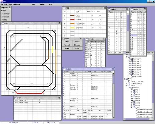
Display track and train information on CTC (MIMIC) windows on the computer screen. These can show which tracks are occupied, which way turnouts are set, which routes are booked, or even list a schedule of future arrivals at a station. The screen-shot on page 1 shows my CTC panels. I use colour to show which train is on what track. Note that some of the turnouts indicate which way they are set (the third leg is invisible), the other turnouts are displaying their default aspect - not showing any direction.
Drive some of the trains so that you can have more activity on the layout than the operators alone could cope with.
You can put these basic operations together so that the computer can:
Act like an intelligent PTP (Point-to-point) unit so that information is copied between a control panel and a layout. Especially useful for areas of track used to hand-over from one operator to another.
Act as a monitoring system, displaying the current track occupancy, signal state etc on the computer screen.
Provide an interlocking function to prevent routes or signals being set if there is a conflict.
Do collision avoidance by cutting power to a track section if a train gets too close to the one in front (this would have no effect on manual control as long as the operators follow the rules).
Display the next operation to perform. Some clubs use a card index or ring binder holding a list of operations for each operator. When all operators have done their tasks they all turn over to the next page. You could get Tcc to recognise when the actions are complete, and display the next actions for each operator.
Display the next entry in a timetable. Which train should arrive or depart from which station, and when.
Remove the need to make control panels - use the computer screen instead (or as well). Useful as a quick prototype to test-run a panel design before making a 'real' panel.
Drive some of the trains to make the layout more active - more visually appealing at an exhibition.
So what does this 'script' look like?
A script consists of declarations (which give names to the interface hardware inputs & outputs and memory variables), and then statements defining what we want Tcc to do.
Example 1
Take a really simple example, one that you might consider implementing with a few gates or a flip-flop. We want a train entering a hidden siding to stop automatically at the end of the siding. On this layout trains always run slowly when approaching the sidings and so we can safely stop them with a simple relay. We can detect their presence with some kind of detector, perhaps a light beam, an infra-red reflective unit like an IRDOT (from Heathcote electronics), a reed relay activated by a magnet on the train, an LDR (light dependant resistor) that changes resistance when light is obscured by a train, or whatever. We want the stationary train to depart again when a button on the control panel is pressed. (assume these are straight through sidings, and that the routes have been set somehow).
Consider the system to have the following:
Inputs:    detector             { A sensor that detects a train }
           release              { A button to restart the train }
Outputs:   stop                 { A relay to disconnect power }
(We will look at the form of the declarations in the second example).
We could define this behaviour with two instructions:
WHEN detector=1 DO stop=1 { stop train when detector is reached }
WHEN release=1 DO stop=0 { start train when called }
These two instructions are like edge-triggered set and reset lines on some kind of theoretical flip-flop.
When a condition becomes true the instructions associated with it are executed once, and then will not be executed again until the condition becomes false, and then true again.
The relay is only set to be energised when the front of the train is detected. After that the first statement is not executed again until the train has departed and another train arrives.
The relay is released when the button is first pressed. The two statements do not 'fight' to control the relay (unless the button is pressed at exactly the same moment that the train arrives, in which case the button wins).
Example 2
As another example suppose we were driving a three aspect signal, and we want it to be driven based upon track occupancy rather than the more complex route selection and interlocking rules.
We want the signal to show red when a train enters the section just after the signal, or when no train is approaching the signal.
We want yellow if the next section is clear, but the one after it is occupied.
And green if both following sections are clear.
OK, you might not like to drive signals that way, but it makes a simple example.
If the sections are called 'A' (before the signal), 'B' (just after the signal) and 'C' (the one after B, and we have inputs that come from an FTC module (Floating Track Circuit, or 8 track occupancy detectors) with the same names.
Assume we also have outputs called red, yellow and green.
One possible script to do this (including the declarations this time) could be:
Constants:
Free=0, Occupied=1, { define the polarity of our sensor inputs }
On=1, Off=0 { define polarity of our outputs }
Sensors:
A, B, C { current detectors attached to sections A, B & C }
Controls:
red, yellow, green { outputs that drive our signal }
Actions:
WHEN A=Free { No train approaching }
OR A=Occupied, B=Occupied { Next section occupied }
DO red=On, yellow=Off, green=Off
WHEN A=Occupied, B=Free, C=Occupied
DO red=Off, yellow=On, green=Off { Train may enter at caution }
WHEN A=Occupied, B=Free, C=Free
DO red=Off, yellow=Off, green=On { Road ahead clear }
|
The text in brackets are just comments, so you can leave notes to remind you how your script works - Tcc ignores them completely.
The section headed 'Constants:' (the first few lines of this script) gives names to numbers, so that we can use On and Off to mean 1 and 0. This aids the readability of the script.
The lines headed 'Sensors:' and 'Controls:' give names to the inputs and outputs that connect to the railway. These are the pins on the FTC and SRO4 modules (or whatever hardware you have chosen to interface to the layout).
After the heading 'Actions:' are the instructions telling Tcc exactly what to do. Each statement consists of the following items:
'WHEN' conditions 'DO' actions
The conditions are simple tests that are and-ed and or-ed together (the commas may be written 'AND', but a comma abbreviates things nicely).
The actions are things we want to happen when the conditions are true.
Note that a script is not really like a programming language - the statements are not executed in order. The script is more like a written version of logic gates and registers. All the 'WHEN' statements are in essence executing in parallel. The script would do exactly the same regardless of the ordering of the three WHEN statements shown above.
The script is largely compatible with the script used by the software that CTI supplies (free download from their web site http://www.cti-electronics.com) and that site has an excellent introduction to these scripts. Tcc adds some advanced capabilities such as structured data and arrays.
How are the input and output lines associated with the names?
They are assigned in the order you list them. The first name is given to the signal on the first bit (bit 0) of the first byte after the stack header, the next seven names to bits 1 to 7. After that the next bit attaches to bit 0 of the next byte, and so on.
Regardless of the style of stack header used (the RPIC reverses the byte stream, the older RPI did not) the first 8 names attach to the first byte of the module closest to the stack header. So the first 8 Sensors (inputs) are the first byte of the input module closest to the stack header, and the first 8 Controls (outputs) are the first byte of the output module closest to the stack header.
You can leave signals unused either by inserting the special name "spare" into the list, or you can configure pins as spare in the network configuration window (explained below).
You tell Tcc about which modules are connected to which stacks, on which serial ports in the Network Configuration window. You can add interfaces (serial ports), change their baud rates (if the stack header permits it), add interface modules, resequence the interfaces and modules and define spare pins in this window.
The Network Configuration window in the screen-shot on page 1 (bottom right-hand window) shows the hardware configuration of my layout when I took the image. The first interface (off the top of the window) is a CTI port that connects to eight TrainBrain modules (a CTI module with four inputs, and four relay outputs). The second interface (labelled 'Merg') connects to my RPC modules: 2 FTCs, 6DPRs and an SRO4 are shown (the rest is off the bottom of the window). The modules are shown in the order they attach to the RPI, starting with FTC-1 in my case.
What can the CTC (or MIMIC) window do?
Firstly Tcc supports upto four CTC windows, just as the CTI software does. Each window is a grid of squares (as many or as few as you wish) and each square can contain a segment of track, some text, or both. A drawing pallette allows you to place segments of track (straight, curved, turnout or crossing) onto the grid. The track can be coloured if desired. Descriptive text can also be added (in three sizes and can be coloured). This text can be longer than the width of a square, and will run over as many squares as is required.
The script can change the colour of the track segments (or groups of segments), it can add text according to what is happening on the layout (such as showing a timetable), and change the colour of the text. It can also change the appearance of turnout and crossing track segments to show which way the turnouts are facing (or which direction the crossing is booked for).
Each square on the CTC panels can also be used as a button, and the script can take action when the mouse is clicked in any given square, perhaps by changing the state of a turnout there, perhaps by booking a route, or even stopping a train.
When you exit Tcc the CTC panel configuration is saved, along with the configuration of modules attached to your serial ports, and the list of windows you have open. It is saved in a file with a .tcp extension. When you launch Tcc it looks for a .tcp file with the same name as your script file so that you can return to the point you left.
You can also save (and reload) CTC panel configurations in a plain text format (File->Save As... ctc).
This might be useful for doing certain edits, or even creating CTC panels automatically.
What exactly can you do in a script?
Apart from inputs and outputs, a script has access to number variables and special functions.
The variables can hold any whole number, a colour, an image number or a pointer to another variable.
In the conditions part of a statement you can do the following:
a. Test inputs for high or low.
b. Test data variables. These can be compared to other variables, or to constant numbers.
c. Test for clicks on Quick Keys. There is a window called QKeys which contains buttons, the labels of which can be defined in the script. When one of these is clicked (left or right button) a script statement can be triggered.
d. Clicks in one (or a range of) squares of a CTC window can trigger script statements.
e. The current clock time, the session time, or layout time can be tested. This can be useful for example in running to a timetable. Clock time is the local real time. Session time is the time since Tcc was started. Layout time can run fast if desired.
The actions part of a statement can do any number of the following:
a. Control output lines. These are all currently single bit variables, though I have plans for multi-bit outputs so that things like signals can appear as a single entity in the script.
b. Update data variables.
c. Put a text message onto a CTC panel. The text can include the values of data variables if desired. You can also set the colour of the text, and erase the text of course.
d. Change the direction of turnouts and crossings on the CTC panels. A turnout can display a default appearance, where all three track segments are shown (like the letter 'Y'), or just the 'normal' or 'reverse' appearance (straight or left or right facing).
e. Change the colour of a single segment of track, or a group of segments in a CTC panel.
f. Load an image file such as a JPEG or GIF and draw it on to a CTC panel. The image can occupy a single square, or a set of squares. It can also be rotated through any angle. These images can be moved, rotated and erased.
g. Set the layout time, and the session time.
h. Pause in the execution of the list of actions in a statement. The delay is local to that one statement and does not affect others. It can delay any number of milliseconds.
i. Pulse an output on, and then sets the output off again.
j. Fetch a random number. This can be used to give the appearance of a complex timetable, when in fact there is no timetable at all!
Sounds like the script and CTC panels can do anything.
That cannot be true. What can't they do?
The main limitation to the scripting language is your imagination. I believe that doing something to your layout in the scripting 'language' is easier to do than in any other programming language, so previous programming experience should not be required.
Another limitation is the bandwidth between the computer and the hardware. For most layout control scenarios this is not a problem, for example even if it took half a second for a signal to change state it would still be quick enough. But it would not be fast enough, if for example you were driving a stepper motor from 4 outputs on an SRO4 module. Using an RPIC you might get 10 messages per second and so you cannot advance the motor more than 10 times a second which might be too slow, depending upon the application.
How do I create a script?
Use any text editor to edit your script, such as Windows 'WordPad', DOS 'edit', or unix's 'vi' or 'emacs'. Tcc does not yet have a script editing window for the main script (though it has one to edit QTU scripts). Someday I will add a script editing window.
Once you have created (and saved) the script, launch Tcc with the command:
java -jar tcc.jar <script filename>
(or make a shortcut on the desktop to run it for you).
Tcc will compile the script and list any errors in the Log window, if there are any. If there are no compile errors Tcc will open any windows that you had open when you last closed down Tcc (using that same script file) and is ready for you to turn on the serial links and run the script.
So we have made a script, but it didn't work first time, what next?
Debugging is built into Tcc.
Firstly you can debug the hardware interfacing to your layout. From the 'View' menu you can launch windows that display Sensors and Controls. By activating each sensor in turn (toggle the switch, wave a magnet over the reed switch, or do whatever is appropriate for your sensors), you can see that the input is correctly wired, and reaching the computer. Also you can manually drive outputs by clicking on buttons in the Controls window, and by doing so you can exercise all the hardware on the layout.
Also, you can view the variables used by the script, as well as the inputs and outputs as the script runs. These windows are available from menus View->Variables, View->Sensors and View->Controls. If a variable or output is in the wrong state then you can change it from the windows. See the screen-dump on page 1 for an example of each of these windows. Note that variables can show symbolic contents as well as numeric ones.
Note that you do not need a layout before writing and testing a script. If the serial ports are turned off (not 'started' in the Configure menu), you can simulate the inputs by clicking the buttons in the Sensors window. This allows you to check out some ideas before actually committing to build the hardware.
If the script runs too fast you can single step it, and see the variables and outputs change. Each time you click the 'Step' button each WHEN statement gets just one chance to run, and then everything wait for you again.
You can also log the execution of the script. This means that as the script runs, a record of what happens is displayed in the log window, and saved to a file called 'tcc.log'. The amount of trace output can be controlled (from a simple indication of which statements have 'fired' to a complete log of which comparisons match and which actions are executed).
Unfortunately there isn't a magic 'fix the bugs in my script' button which makes the script do what you wanted it to do, rather than what you actually told it to do. If you know how to do one, I'd certainly like to know!
So can you really drive trains automatically?
If you have some computer controlled throttles you can.
All throttle types appear the same to the script. Each has a speed setting, inertia, brake and direction controls. These function in the same manner as the knobs and switches on a manual railway controller.
In order to tell Tcc about the throttles we use another section of the declarations at the start of the script. Such a declaration might look something like:
SmartCabs:
c1, c2, c3
Which defines three computer controlled throttles (of any of the kinds listed in section 2). This gives the script access to the following variables;
c1.speed, c1.brake, c1.inertia, c1.direction, c2.speed etc...
With this you can control the power output of each of the throttles, and with relays you can route the power to where it is required.
The automatic train parking script (example 1 in section 4) could be changed to drive the brake on one such throttle instead of dropping a relay. The train would then decelerate and accelerate smoothly instead of stopping suddenly (and perhaps derailing).
How fast does the script run?
On my machine I run an enormous script of some 1400 WHEN statements in a 3400 line script file and on an 800MHz AMD machine it would execute the whole script 700 times a second. Yes, every test of every statement is evaluated that fast. That's lots faster than I need - even with a QTU running at 57600 baud I only get 45 messages per second. So anything over 100 loops of the script per second cannot do much as the inputs cannot have changed in that time (or at least such changes cannot have been read by the computer).
In fact Tcc regulates the speed that the script runs at. An idle script will run around 50 times a second, and a busy script several times that speed. This is so that Tcc does not simply consume all the CPU it can and make the system unresponsive to other applications.
So what sort of computer do you need to run Tcc?
Tcc is written in Java (which is why you can run it on Linux, Solaris, Mac and Windows). I do my development on a Mac, and then run the layout on a Windows 98 PC.
Whatever the computer hardware, you need a machine with one or more serial ports. This might mean getting a plug-in card or a USB to serial adaptor.
You need 128Mbytes of RAM if you are running Windows 98. Later versions may require more. The key thing is that you have enough memory for the operating system to run in without needing to swap code in and out, and then perhaps 10-15Mbytes for Tcc. If the operating system swaps things in and out of memory it will cause problems with the serial interface, and the RPIC can crash (or at least older RPIC code would).
I would guess that a Linux machine could run with less memory, but I have no personal experience with java on Linux.
Shorter scripts than mine (mentioned above) will run proportionally faster and so you really shouldn't need such a modern machine. Even a good '486 should be adequate for most purposes (as long as you have the memory).
If you want complex CTC panels then you will want a screen resolution rather better than 640 by 480, but you can grow into that in time.
You will need a Java virtual machine installed (java 2 version 1.3 or later) which is available as a free download from http://java.sun.com
You will also need to download the Java comms package (which is another free download that adds access to serial and parallel ports). You only need the JVM (runtime Java Virtual Machine), and not the full SDK (Software Development Kit) unless you want to write your own java programs. the SDK download is MUCH bigger.
I have tested Tcc on Java 2 version 1.4.1 (which fixes some bugs) and so it is probably a good idea to download that if you are downloading java, or better still get it on CD as the download can take a while if you do not have broadband. When Java version 1.5 comes out (part is in alpha testing) I'll probably have to stop testing on 1.3 and concentrate on 1.4 and 1.5.
Where can I get a copy of Tcc?
On the yahoo groups site, in the files area:
http://groups.yahoo.com/group/mergtcc/files/Tcc_V1.5/tcc.jar Look for other folders called Tcc_yy_mm_dd for interim builds.
In addition there is a copy of (an older version of) my monster script, called ha1.tcl. Do not expect to understand how it works - it is enormous, and it was generated automatically. I have uploaded it so you can check syntax, and look for examples in it, but read the CTI documentation first - they have done a good job of introducing the scripting language. One day I'll write a few extra chapters that define the extras that Tcc provides.
What plans are there for future upgrades?
I have several ideas, in no particular order:
1. Add a TCL script editing window, so that you don't have to use a separate editor.
2. Allow scripts to play sounds. Ideally I would like to play several sounds at the same time, out of different ports. With a 5.1 surround sound card, and each output routed through relays to loudspeakers all around the layout you should be able to make a really good sound effect.
3. Display CTC panels on remote computers. This would allow monitoring be several operators, or even a display could be dedicated to showing the current timetable at an exhibition for example.
4. Permit more natural expressions in the statements (such as DO a=b+3), rather than the restrictive forms adopted from the CTI language.
If I were to find something that was particularly useful on a model railway, and could not be done with Tcc (or was exceptionally difficult) then I'd probably extend the software to make it easy.
If you feel any of the above might be useful, then do have a go. Read the CTI tutorial, download Tcc or the CTI software, write a script, and if you think some improvement might be achieved for your layout, then connect it all up and experiment. If you have any problems then like-minded experimenters that inhabit the yahoo group will probably have the answers you need!